
Achieving peak efficiency in your wireless deployments begins with a deep dive into s11 in antenna metrics, the fundamental measure of signal reflection and power transfer. By accurately evaluating s11 in uhf rfid antenna systems and understanding the critical nuances between real life s11 and simulation, engineers can significantly reduce energy loss and maximize the read range of their industrial RFID infrastructure.
Introduction: What is S11 and Why Does It Matter?
In the complex world of Radio Frequency (RF) engineering, precision is the cornerstone of connectivity. For professionals managing large-scale wireless systems, understanding the fundamental metrics of signal integrity is essential. One of the most critical parameters in this domain is S11, also known as the reflection coefficient.
At its core, S11 is a measurement used to quantify the efficiency of power transfer between an RF transmitter and its antenna. When a signal is sent through a system, a portion of that energy is successfully radiated by the antenna, while the remainder is reflected back toward the source due to impedance mismatches. S11 specifically measures the ratio of this reflected power versus the power delivered to the antenna. In practical terms, a lower S11 value indicates a more efficient match, ensuring that the maximum amount of energy is utilized for communication rather than being wasted as heat or potential interference.
Why does this technical metric matter for your operations? In the context of industrial RFID systems, S11 serves as a primary indicator of hardware health and system performance. Consider the following implications of S11 optimization:
- Signal Reliability: A well-optimized S11 ensures that RFID readers can maintain a consistent connection with tags, even in high-density environments.
- Hardware Longevity: Excessive reflected power can cause strain on sensitive RF components, leading to premature hardware failure and increased maintenance costs.
- Read Range Efficiency: Minimizing reflections maximizes the effective radiated power, which directly translates to longer and more accurate read ranges in the field.
At Nextwaves Industries, we specialize in high-performance RFID hardware where S11 optimization is a non-negotiable standard. Our UHF RFID antennas, readers, and tags are engineered to meet the rigorous demands of logistics, manufacturing, and supply chain modernization. We understand that in a fast-paced warehouse or a complex cold chain environment, every decibel of performance counts. By prioritizing superior RF design and S11 precision, Nextwaves provides the reliability and end-to-end visibility necessary to keep your global operations moving forward without interruption.
The S11 Scorecard: Deciphering the Numbers
Understanding the S11 parameter is critical for assessing how much power is actually being transmitted by your RFID hardware versus how much is being reflected back to the reader. Because S11 is measured on a logarithmic scale in decibels (dB), the values can initially seem counterintuitive: a more negative number indicates a more efficient antenna system.
To interpret these readings, it is helpful to look at the two theoretical extremes. A perfect antenna-one that radiates 100% of the energy it receives-would have an S11 value of negative infinity (-∞ dB). On the opposite end of the spectrum, an S11 value of 0 dB indicates that 100% of the power is being reflected, meaning no energy is being transmitted to your RFID tags. For professional-grade deployments in logistics and manufacturing, we categorize performance into three primary tiers:
| Performance Tier | S11 Value (dB) | VSWR | Reflected Power | Good Match | Less than -10 dB | < 2.0:1 | < 10% | Marginal Match | -6 dB to -10 dB | 2.0:1 to 3.0:1 | 10% to 25% | Poor Match | Greater than -6 dB | > 3.0:1 | > 25% |
|---|
At Nextwaves Industries, we strive for a Good Match (S11 < -10 dB) in all our UHF RFID antenna installations. When your system operates within this tier, you ensure that over 90% of the power is successfully delivered to the antenna. This efficiency is what drives the high-speed read rates and long-range visibility required for modern supply chain modernization.
If your scorecard shows a Poor Match, your system is suffering from significant signal loss. This not only reduces the operational range of your readers but can also cause reflected energy to heat up and potentially damage sensitive RFID hardware. Monitoring these metrics is the first step toward achieving the intelligent, end-to-end visibility that Nextwaves solutions provide.
UHF RFID Specifics: The Challenge of Complex Impedance
In the specialized world of Ultra-High Frequency (UHF) RFID, which typically operates within the 860-960 MHz band, the standard rules of RF engineering take a unique turn. While most traditional wireless systems-such as Wi-Fi, cellular, or Bluetooth-are designed around a standardized 50-ohm characteristic impedance, RFID tags operate on the principle of complex conjugate matching. This departure from the 50-ohm norm is essential for the passive nature of RFID technology, where every milliwatt of harvested energy is critical for performance.
The primary challenge stems from the electrical characteristics of the RFID integrated circuit (IC). These chips are inherently highly capacitive. In a passive system, the chip must harvest enough power from the reader's signal to wake up and transmit its data. To ensure maximum power transfer from the antenna to the IC, the antenna's impedance must be the mirror image, or complex conjugate, of the chip's impedance. If the RFID chip has an impedance of Z = R - jX (representing its resistive and capacitive components), the antenna must be engineered with an impedance of Z = R + jX (resistive and inductive).
Because the chip is capacitive, the antenna must be designed as a predominantly inductive component to achieve resonance. This is why S11 measurements in RFID are so distinct; we are not looking for a match to 50 ohms, but rather a perfect alignment with the specific reactive profile of the silicon. To achieve this inductive balance, Nextwaves Industries utilizes several sophisticated design architectures:
- T-Match Structures: By adding a secondary, parallel conductor to the main dipole and connecting them at specific points, we can precisely tune the input impedance to match the IC.
- Inductive Loops: Incorporating a small loop near the feed point of the antenna provides the necessary inductance to cancel out the chip's high capacitance, allowing the system to resonate at the target frequency.
- Folded Dipoles: These structures allow for higher impedance values that more closely align with the requirements of modern, high-sensitivity RFID chips.
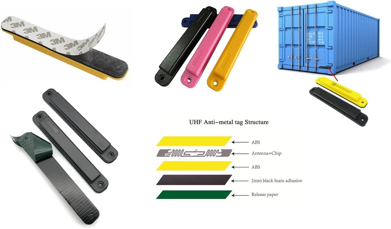
At Nextwaves Industries, we understand that a "good" S11 reading is relative to the environment and the specific hardware pairing. Our UHF RFID antennas are engineered to maintain this complex match even when applied to challenging materials like glass, plastic, or liquid-filled containers. By mastering the challenge of complex impedance, we provide our partners in manufacturing and logistics with high-performance hardware that ensures superior read rates and end-to-end visibility across the entire supply chain.
| System Type | Standard Impedance | Matching Requirement | Standard RF (Wi-Fi/Cellular) | 50 Ohms (Real) | Match to 50-ohm Transmission Line | UHF RFID (Passive Tags) | Complex (e.g., 15 - j150 Ohms) | Complex Conjugate (Antenna must be Inductive) |
|---|
By optimizing these inductive components, Nextwaves Industries ensures that our RFID solutions deliver maximum operational efficiency, providing the high-performance hardware necessary for modern dispatch management and inventory systems.
Environmental Sensitivity: Why S11 Shifts in the Real World
In a controlled laboratory setting, an RFID tag might exhibit textbook performance with a near-perfect impedance match. However, the "real world" is rarely as accommodating as a test bench. When a tag is deployed in high-velocity logistics or complex retail environments, it encounters various materials that fundamentally alter its electromagnetic profile. This phenomenon, known as dielectric loading, occurs because the material an antenna is attached to-such as cardboard, plastic, or wood-changes the electrical environment, effectively "detuning" the antenna.
Research data highlights the severity of this shift. An RFID tag designed for "free air" may demonstrate an exceptional S11 value, but that performance often collapses once it is applied to a physical asset. Consider the following performance comparison:
| Environment/Material | S11 Measurement (dB) | Power Reflected back to Source | Free Air (Ideal) | -20 dB | ~1% (Excellent) | Corrugated Cardboard | -10 dB | ~10% (Acceptable) | High-Density Plastic/Moisture | -2 dB | ~63% (Critical Failure) |
|---|
As shown above, a shift from -20 dB to -2 dB represents a catastrophic loss in efficiency. At -2 dB, the majority of the signal power is reflected away from the antenna rather than being absorbed by the RFID chip. This leads to missed reads, reduced range, and "blind spots" in your supply chain. These challenges are particularly prevalent in specific sectors:
- Cold Chain: Condensation and ice act as significant dielectric loads, frequently detuning tags and making inventory tracking difficult in refrigerated environments.
- Logistics: Dense stacking of varied materials (liquids, metals, and polymers) creates a volatile RF environment where S11 values fluctuate constantly.
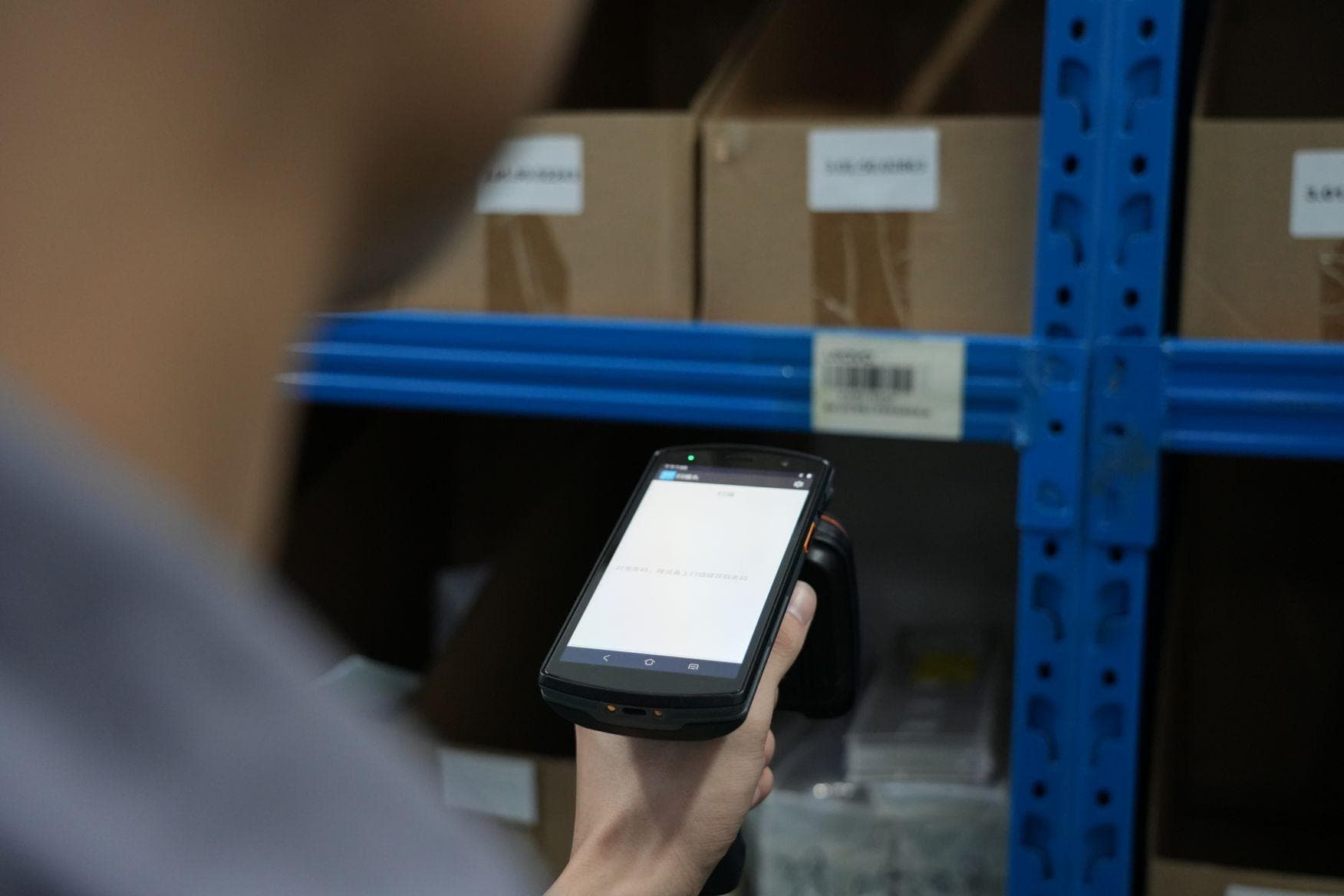
- Retail: Product packaging with metallic foils or high liquid content can shift the resonant frequency of a standard tag, rendering it unreadable by handheld scanners.
At Nextwaves Industries, we understand that S11 isn't just a static number on a spec sheet; it is a dynamic variable that must be managed. Our value proposition lies in bridging the gap between theoretical physics and operational reality. By utilizing high-performance UHF RFID hardware and intelligent software systems, we ensure end-to-end visibility even when environmental factors push S11 values to their limits. We don't just provide tags; we provide a robust communication ecosystem designed to maintain 100% accuracy in the most demanding physical conditions.
Simulation vs. Measurement: Bridging the Engineering Gap
In the initial stages of antenna design, engineering teams rely heavily on sophisticated electromagnetic simulation software such as CST Studio Suite or Ansys HFSS. These tools provide a theoretical playground where S11 parameters can be optimized in a vacuum or idealized environment. However, at Nextwaves Industries, we understand that a "perfect" simulation is merely a starting point. The true test of an RFID antenna occurs when it moves from the digital canvas to the Vector Network Analyzer (VNA) for physical measurement.
Discrepancies between a simulated S11 curve and a measured one are common and often significant. Bridging this engineering gap requires a deep understanding of several variables that are frequently simplified or omitted in theoretical models. Below are the primary factors that cause real-world measurements to deviate from their digital twins:
- Frequency-Dependent Dielectric Properties: Many substrate materials, such as FR4 or specialized polymers used in RFID tags, exhibit permittivity (εr) and loss tangents that fluctuate across the UHF spectrum. Simulations often use static values, leading to a shift in the resonant frequency during physical testing.
- Parasitic Effects: Real-world measurements include the influence of RF connectors, solder joints, and the coaxial cables used to connect the antenna to the VNA. These components introduce parasitic capacitance and inductance that can alter the impedance match and degrade the S11 return loss.
- Housing and Environmental Impact: The thickness of a plastic radome, the chemical composition of a protective coating, or the proximity of a metal chassis can "detune" an antenna. While these can be modeled, the microscopic tolerances in manufacturing often lead to unexpected shifts in the S11 dip.
- Adhesives and Inlays: In RFID tag manufacturing, the adhesives used to bond an inlay to a surface are often omitted in simulations. However, these thin layers of adhesive act as a dielectric that can significantly impact the electrical length of the antenna.
| Feature | Simulation (CST/HFSS) | Measurement (VNA) | Environment | Idealized or Vacuum | Real-world interference & reflections | Material Values | Nominal/Static | Tolerance-based/Frequency-dependent | Interconnects | Perfect Port Feeds | Cables, Connectors, and Soldering |
|---|
At Nextwaves Industries, our hardware engineering process involves iterative cycles of simulation followed by rigorous VNA validation. By accounting for these real-world variables early in the design phase, we ensure that our high-performance UHF RFID hardware delivers consistent, reliable visibility for logistics and supply chain modernization, even in the most challenging industrial environments.
Conclusion: Engineering Efficiency with Nextwaves
Understanding S11 (Return Loss) is more than a technical exercise; it is the foundation of a high-performing RFID ecosystem. By minimizing signal reflection and maximizing power transfer between the reader and the antenna, businesses can ensure consistent read rates even in the most challenging radio frequency (RF) environments. For manufacturing and logistics leaders, a low S11 value translates directly into reduced downtime, fewer missed scans, and a more reliable data stream across the supply chain.
At Nextwaves Industries, we specialize in bridging the gap between complex RF physics and seamless operational execution. Our suite of UHF RFID Antennas and Readers is engineered to maintain peak performance under real-world conditions, effectively overcoming common issues like interference and signal bounce. By prioritizing hardware integrity, we provide our clients with a robust physical layer that serves as the backbone for digital transformation.
True supply chain modernization requires more than just high-quality hardware. Nextwaves integrates these high-performance components with intelligent software solutions, such as our proprietary Dispatch Management and Inventory Systems. This holistic approach ensures that your data is not only captured accurately but also utilized effectively to drive decision-making. Our expertise covers:
- End-to-End Visibility: Achieving real-time tracking from the factory floor to the warehouse and through the final mile.
- Optimized RF Environments: Deploying hardware and software configurations that mitigate the impact of metallic reflections and environmental noise.
- Industry-Specific Scalability: Tailoring RFID solutions to meet the rigorous demands of the Retail, Cold Chain, and Heavy Logistics sectors.
Don't let poor signal performance or RF interference hinder your operational growth. Partner with Nextwaves Industries to leverage our deep expertise in RFID technology and software integration. Improve your operational efficiency today by deploying end-to-end solutions designed for precision, reliability, and long-term supply chain success.
Was this article helpful?
Related Articles
Maximizing Asset Visibility: The Ultimate Guide to Anti-Metal UHF RFID Tags
Mar 2, 2026
Mastering UHF RFID in Odoo: Hardware, Workflows, and Best Practices
Mar 2, 2026
Chainway C72 Comprehensive Review: Specs, Pricing, and Top Alternatives
Mar 2, 2026

The Ultimate UWB Module Comparison: Prices, Specs, and Use Cases
Feb 23, 2026